- 您现在的位置:买卖IC网 > Sheet目录307 > ADE7758ARWZRL (Analog Devices Inc)IC ENERGY METERING 3PHASE 24SOIC
Data Sheet
START
STEP 1
ENABLE CF
OUTPUTS
STEP 2
CLEAR OFFSET
REGISTERS
xWATTOS, xVAROS
ADE7758
YES
ALL PHASES
WATT OFFSET
CALIBRATED?
NO
STEP 3
SET UP APCF
PULSE OUTPUT
FOR PHASE A, B,
OR C
END
YES
ALL PHASES
VAR OFFSET
CALIBRATED?
NO
STEP 3
SET UP VARCF
PULSE OUTPUT
FOR PHASE A, B,
OR C
SELECT PHASE
FOR LINE PERIOD
MEASUREMENT
STEP 4
SET UP SYSTEM
FOR I MIN , V NOM ,
PF = 1
STEP 5
MEASURE %
ERROR FOR
APCF
STEP 6
CALCULATE AND
WRITE TO
xWATTOS
CONFIGURE
FREQ[11:0] FOR A
LINE PERIOD
MEASUREMENT
STEP 7.
REPEAT STEP
3 TO STEP 6
FOR xVAROS
STEP 4
SET UP SYSTEM
FOR I MIN , V NOM ,
PF = 0, INDUCTIVE
STEP 5
MEASURE %
ERROR FOR VARCF
MEASURE PERIOD
USING FREQ[11:0]
REGISTER
STEP 6
CALCULATE AND
WRITE TO
xVAROS
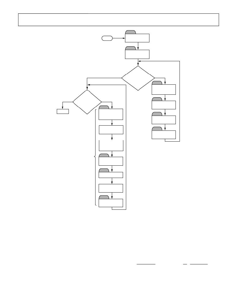
Figure 80. Offset Calibration Using Pulse Output
Step 1: Repeat Step 1 and Step 3 from the gain calibration to
configure the ADE7758 pulse output.
Step 2: Clear the xWATTOS and xVAROS registers.
Step3: Disable the Phase B and Phase C contribution to the APCF
and VARCF pulses. This is done by the TERMSEL[2:4] bits of
the COMPMODE register (0x16). Setting Bit 2 to Logic 1 and
Bit 3 and Bit 4 to Logic 0 allows only Phase A to be included in
the pulse outputs. Select Phase A, Phase B, or Phase C for a line
Step 4: Set the test system for I MIN , V NOM , and unity power factor.
For Step 6, set the test system for I MIN , V NOM , and zero-power
factor inductive.
Step 5: Measure the percent error in the pulse output, APCF or
VARCF, from the reference meter using Equation 49.
Step 6: Calculate xWATTOS using Equation 56 (for xVAROS
use Equation 57).
xWATTOS =
? %APCF ERROR
?
? 2
× APCF EXPECTED ? × ×
period measurement with the FREQSEL[1:0] bits in the MMODE
register (0x14). For example, clearing Bit 1 and Bit 0 selects
Phase A for line period measurement.
– ?
100 %
? Q
4
APCFDEN
APCFNUM
(56)
Rev. E | Page 47 of 72
发布紧急采购,3分钟左右您将得到回复。
相关PDF资料
ADE7761AARSZ-RL
IC ENERGY METERING 1PHASE 20SSOP
ADE7761BARSZ-RL
IC ENERGY METERING 1PHASE 20SSOP
ADE7768ARZ-RL
IC ENERGY METERING 1PHASE 16SOIC
ADE7769ARZ-RL
IC ENERGY METERING 1PHASE 16SOIC
ADM8843ACPZ-REEL7
IC LED DRVR WHITE BCKLGT 16LFCSP
ADP1653ACPZ-R7
IC LED DRVR PHOTO FLASH 16-LFCSP
ADP1712-EVALZ
BOARD EVALUATION ADP1712
ADP1720-EVALZ
BOARD EVAL FOR ADP1720-ADJ
相关代理商/技术参数
ADE7759
制造商:AD 制造商全称:Analog Devices 功能描述:Active Energy Metering IC with di/dt Sensor Interface
ADE7759ARS
功能描述:IC ENERGY METERING 1PHASE 20SSOP RoHS:否 类别:集成电路 (IC) >> PMIC - 能量测量 系列:- 产品培训模块:Lead (SnPb) Finish for COTS
Obsolescence Mitigation Program 标准包装:2,500 系列:*
ADE7759ARSRL
功能描述:IC ENERGY METERING 1PHASE 20SSOP RoHS:否 类别:集成电路 (IC) >> PMIC - 能量测量 系列:- 产品培训模块:Lead (SnPb) Finish for COTS
Obsolescence Mitigation Program 标准包装:2,500 系列:*
ADE7759ARSZ
功能描述:IC ENERGY METERING 1PHASE 20SSOP RoHS:是 类别:集成电路 (IC) >> PMIC - 能量测量 系列:- 产品培训模块:Lead (SnPb) Finish for COTS
Obsolescence Mitigation Program 标准包装:2,500 系列:*
ADE7759ARSZRL
功能描述:IC ENERGY METERING 1PHASE 20SSOP RoHS:是 类别:集成电路 (IC) >> PMIC - 能量测量 系列:- 产品培训模块:Lead (SnPb) Finish for COTS
Obsolescence Mitigation Program 标准包装:2,500 系列:*
ADE7760
制造商:AD 制造商全称:Analog Devices 功能描述:Energy Metering IC with On-Chip Fault Detection
ADE7760ARS
制造商:Analog Devices 功能描述:Energy Measurement 20-Pin SSOP 制造商:Analog Devices 功能描述:ENERGY METER IC W/ ONCHIP FAULT & OSCIL. - Rail/Tube
ADE7760ARSRL
制造商:Analog Devices 功能描述:Energy Measurement 20-Pin SSOP T/R 制造商:Analog Devices 功能描述:ENERGY METER IC W/ONCHIP FAULT & OSCIL. - Tape and Reel
